
Roller Bearing Lubrication Simulation
The following blog post will give you some insights on how the particle based CFD method Smoothed Particle Hydrodynamics (SPH) is used to predict oil lubrication phenomena in roller bearings.
Such simulations are influenced by large differences in scale regarding time and space. Therefore, classical mesh based CFD approaches, e.g. the finite-volume method, come with challenging preprocessing workflows and high computational runtimes. But how is SPH different?
The SPH method is a perfect pick for industrial usage when it comes to moving geometries or dynamic free surface flows. Furthermore, it comes with high computational scalability if the respective hardware resources are available. Its capabilities to treat dynamic phase interfaces in a more natural way come in especially handy for roller bearing simulations. These capabilities result from its Lagrangian meshfree nature.
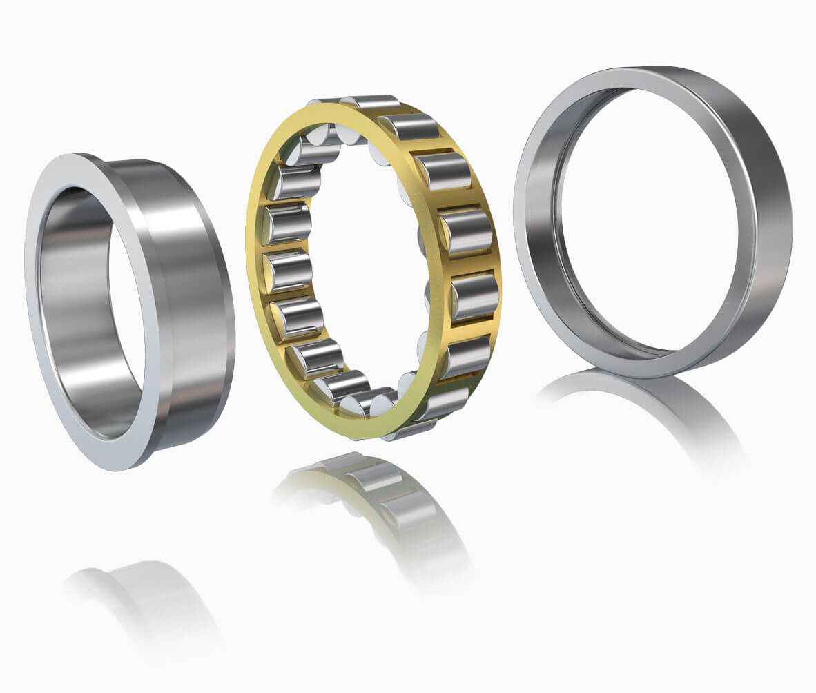
In this article, we want to give you some insights on the collaboration between Schaeffler Technologies AG & Co. KG and dive solutions GmbH. Within this close collaboration we were able to present the very first SPH roller bearing simulations to the world of engineering. The ambitious project also involved a set of essential software innovations such as local particle refinement, periodic boundary conditions, highly complex wall boundary treatments, and multiphase flows.
Technical challenges of bearing simulation
Before getting into the details of SPH simulations, we want to discuss some of the major challenges for bearing simulations in general. Roller bearings are standardized mechanical components to mount and position shafts and axles. They are used in very large numbers, in various designs, and in many different applications. Now let us have a look at the acting physical phenomena behind such an essential mechanical component. There are multiple dynamic effects coming together in roller bearing operations. For example, the distance between rolling elements and running surfaces is changed cyclically over one revolution when the rolling element enters the load zone. At the same time, the speeds of the individual rolling elements change due to the accelerations acting on them.
But why exactly is fluid simulation relevant for finding a feasible design? Within the scope of the development and optimization as well as the return analysis of roller bearings, questions regarding the internal fluid flow are often focusing on the following points:
- Fluid distribution
- Torque and churning losses
- Pressure resistance
- Influence of geometric changes
To get a good feeling for how these measures can be successfully predicted, we need to dive into the very details of the flow phenomena. First, flows in roller bearings are complex: three-dimensional, multiphase, transient. Both turbulent and laminar flow areas occur simultaneously. Additionally, the consideration of significantly different time and length scales is a challenge for the numerical simulation. In roller bearings, differences of up to seven powers of ten typically occur between the smallest and the largest geometric length scale, i.e. the lubrication gap height and the outer diameter.
The flow processes in roller bearings are also characterized by strongly varying time scales: The time difference between the rotation of a rolling element and the formation of a thermal equilibrium are in the region of about six powers of ten. But that is not enough. The highest speeds in roller bearings occur in the lubrication gap. To calculate the flow in this essential area, numerical time steps in the range of 10-7 s are required. It follows that a single roller bearing revolution requires 105...106 time steps. Without further measures, the simulation of the roller bearing flow in an industrial environment is practically impossible. It’s okay if this makes you feel dizzy. We feel the same.
Today, roller bearings are mostly simulated with the finite volume method using a RANS turbulence model on spatially fixed calculation grids. The volume of fluid method is used for the modelling of multiphase flows. Moreover, it is state-of-the art to use a segment approach to reduce computational effort. Assuming axis symmetry and periodicity, only a single roller bearing segment is simulated. These simplifications allow a much higher local resolution of the flow. At the end, this gives us the power to increase the accuracy of our numerical prediction.

It is obviously necessary to find suitable approaches that simplify the simulation models and shorten simulation times. There are three approaches:
- simplifying the geometry,
- simplifying the physics, and
- accelerating the numerical solution.
We can take either one or multiple measures to make the roller bearing simulation feasible. However, a simplified model always leads to a reduction in the level of simulation detail. Therefore, the range of engineering questions that can be answered is also limited. The appropriate degree of simplification is always determined by the specific technical problem to be investigated.
The novel approach: SPH roller bearing simulation
So, this is the part you have been waiting for. How is SPH performing when it encounters such a complex fluid mechanical problem? To get started with SPH, we should take a quick look at its meshfree property.
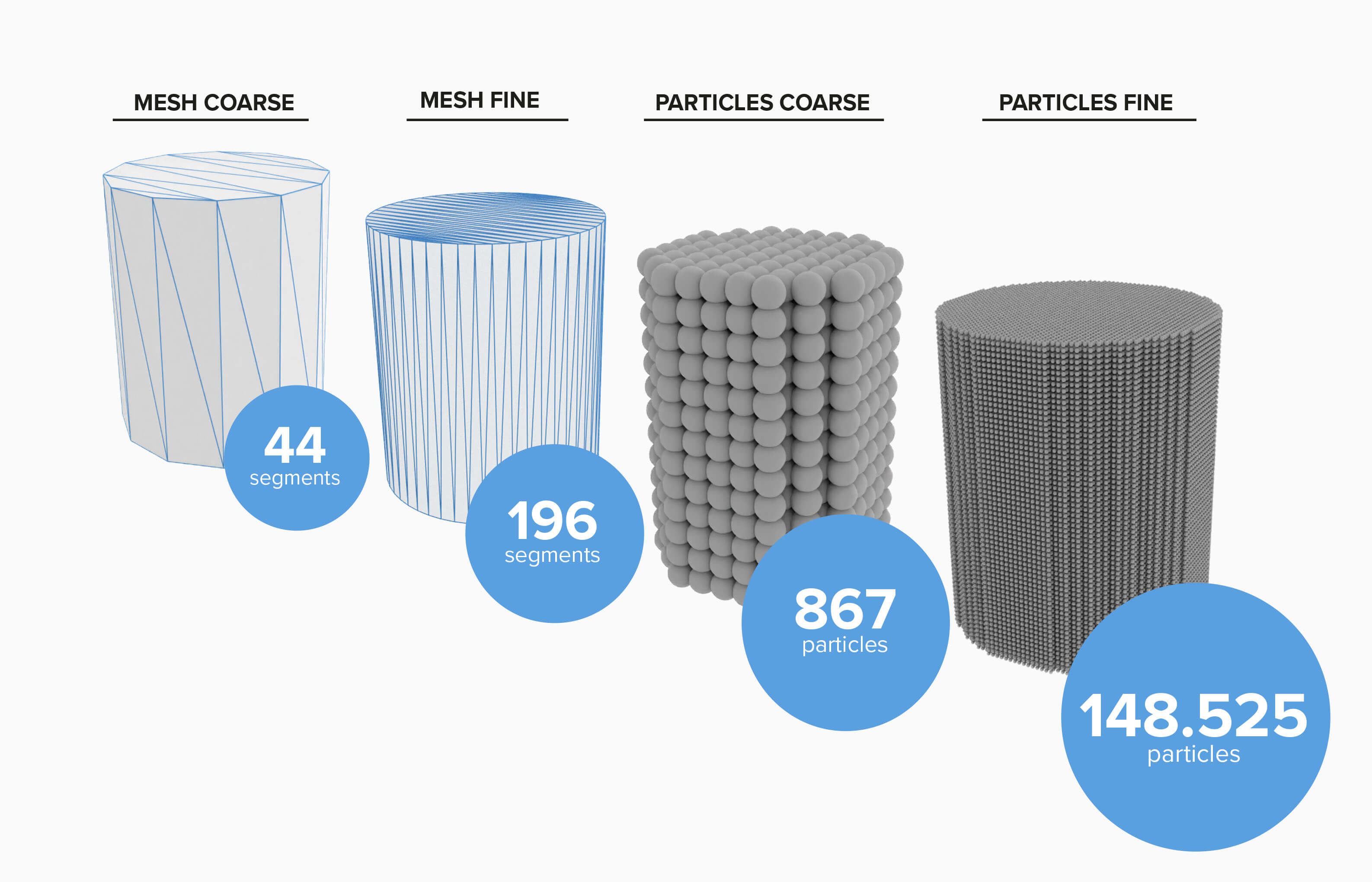
SPH is based on the lagrangian formulation of the basic fluid mechanics equations. This allows the simulation of dynamic multiphase processes without the complex grid generation.¹ This is of particular importance for geometrically or physically complex processes such as roller bearing flows. Typically, several days or even weeks of work can be saved in the simulation process. The sharp separation between different fluids allows interfaces to be reconstructed with high robustness and physical accuracy. Especially for processes driven by effects such as surface tension or strong interactions between different phases, this a critical advantage. To learn more about the SPH method, check out this article which breaks down its key properties in detail.
These advantages pave the way for the industrial use of Smoothed Particle Hydrodynamics. SPH is a flexible tool, prepared for a wide range of application scenarios in everyday industrial life (free surfaces, multiphase systems, closed systems). SPH enables fast, automated simulations of different design variations with industrial accuracy.
Figure 3: Basic Idea of SPH


Classical Challenges of Using SPH Simulations
However, many CFD experts have so far considered SPH to be a rather inaccurate method, mainly suitable for qualitative or visual studies. Why is that?
Compared to classical multiphase CFD approaches (such as the volume of fluid method), SPH is a rather young simulation method. For a long time, many well-known numerical concepts or models were not available in SPH at all or only in insufficient quality. This limited its industrial applicability. In roller bearing simulation, the following points were critical:
- Missing models for the simulation of periodic systems
- Missing models for the simulation of multiphase systems
- Low accuracy of the wall boundary treatment
- Missing models for particles of different sizes
- Missing models for the simulation of closed systems
But what is the point of a close collaboration if not to team-up and overcome these limitations together? An intensive, agile collaboration was initiated, which addressed all of these issues over several months. The outcome: Based on the combination of numerical and application know-how, we made roller bearing simulations with SPH possible.
Status Quo: Wall Boundaries in SPH
For CFD users, one aspect is crucial for the quality of the results: the modeling of solid boundaries. For a long time, the low quality of the boundary treatment was a major weakness of SPH in industrial use cases. According to the nature of SPH, simple approaches follow the idea of modelling walls with particles. But this does not correspond to the general numerical representation of digital models. Hence, it leads to dramatic geometric inconsistencies. Recent developments have made a new type of boundary treatment possible: surface-based boundaries.1
These boundaries have several decisive advantages over classical approaches
- More accurate representation of the original geometry
- Reduced number of numerical interpolation points
- High numerical accuracy
Using this modern boundary treatment was a key aspect in making the simulation of the complex roller bearing flow possible.
The Final Simulation Model
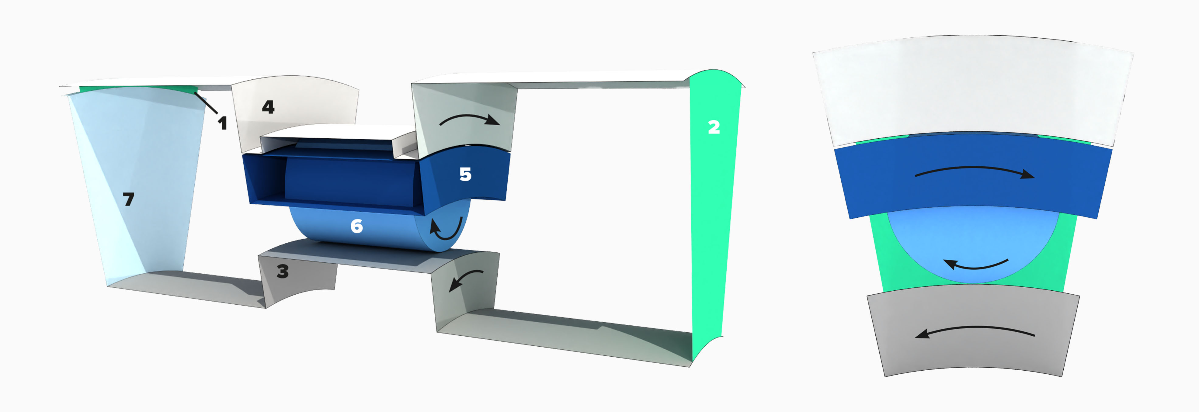
Now, let’s have a look at the details of our simulation setup. As described in the first chapter, a reduction of the simulation system is essential for guaranteeing the required resolutions in the rolling element area. The system setup is shown in the following figure.
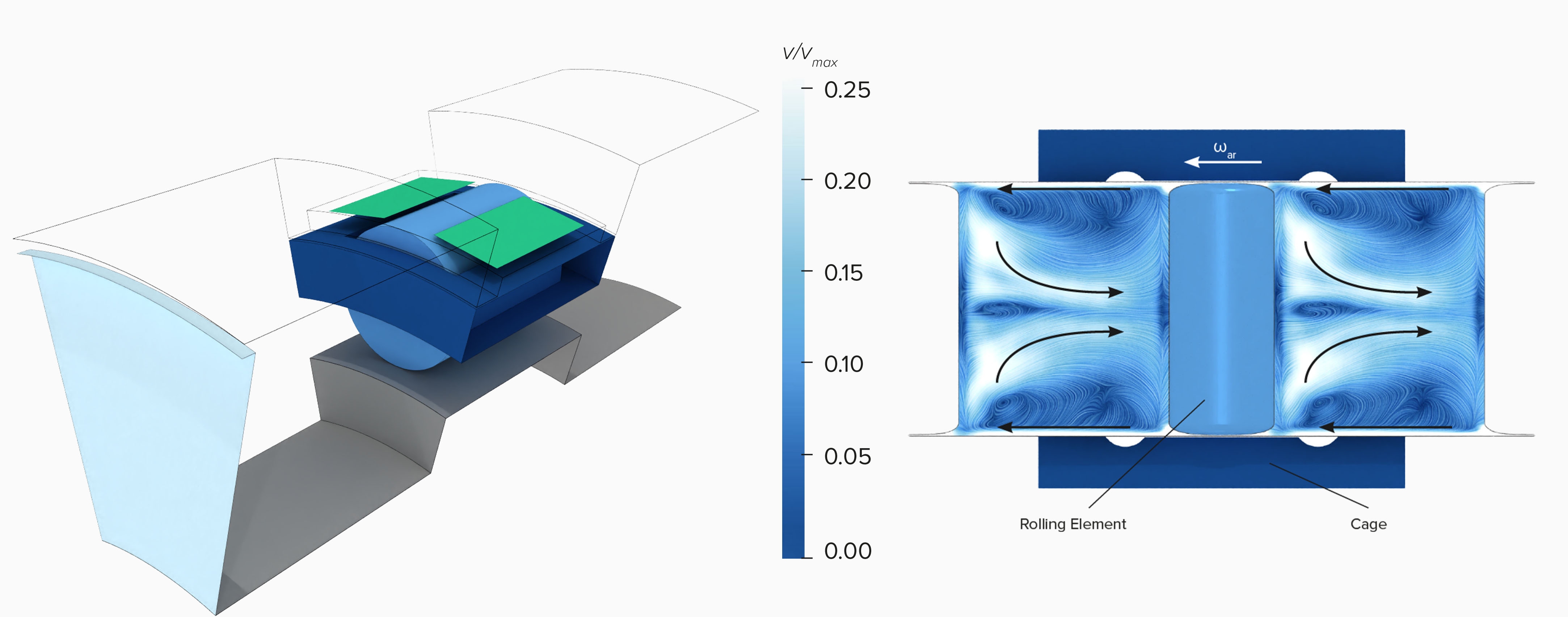
Some advanced SPH models are required here. The system size is drastically reduced by periodic boundaries and an inertial system that moves with the rolling element. High-quality open boundaries (1,2) ensure that boundary values are accurately imposed, and that acoustics leave the system as expected. The segment-based boundary provides an exact representation of the rolling element geometry. It enables virtually moving no-slip surfaces (3), (4), (5), (6) as well as solid slip surfaces (7).
Results
We talked about the setup and the decision-making process. Now it is time to have a look at the actual results. In this short article we want to focus on the single phase simulation of a cylindrical roller bearing. Approx. 4 million particles were simulated in this setup. We assume that gravity and the influence of the geometry change are negligible.
The Single phase Simulation Results
The following figure gives a first impression of the flow conditions in the bearing. We are in the rolling elements reference system and rotate with it around the Z-axis. Due to the strong centrifugal forces, the oil is agglomerated in the outer region. High rotational speeds enforce the main flow direction in circumferential direction. The flow through the bearing runs from left to right. In the selected reference system, the cage is stationary, and the rolling element rotates around itself.
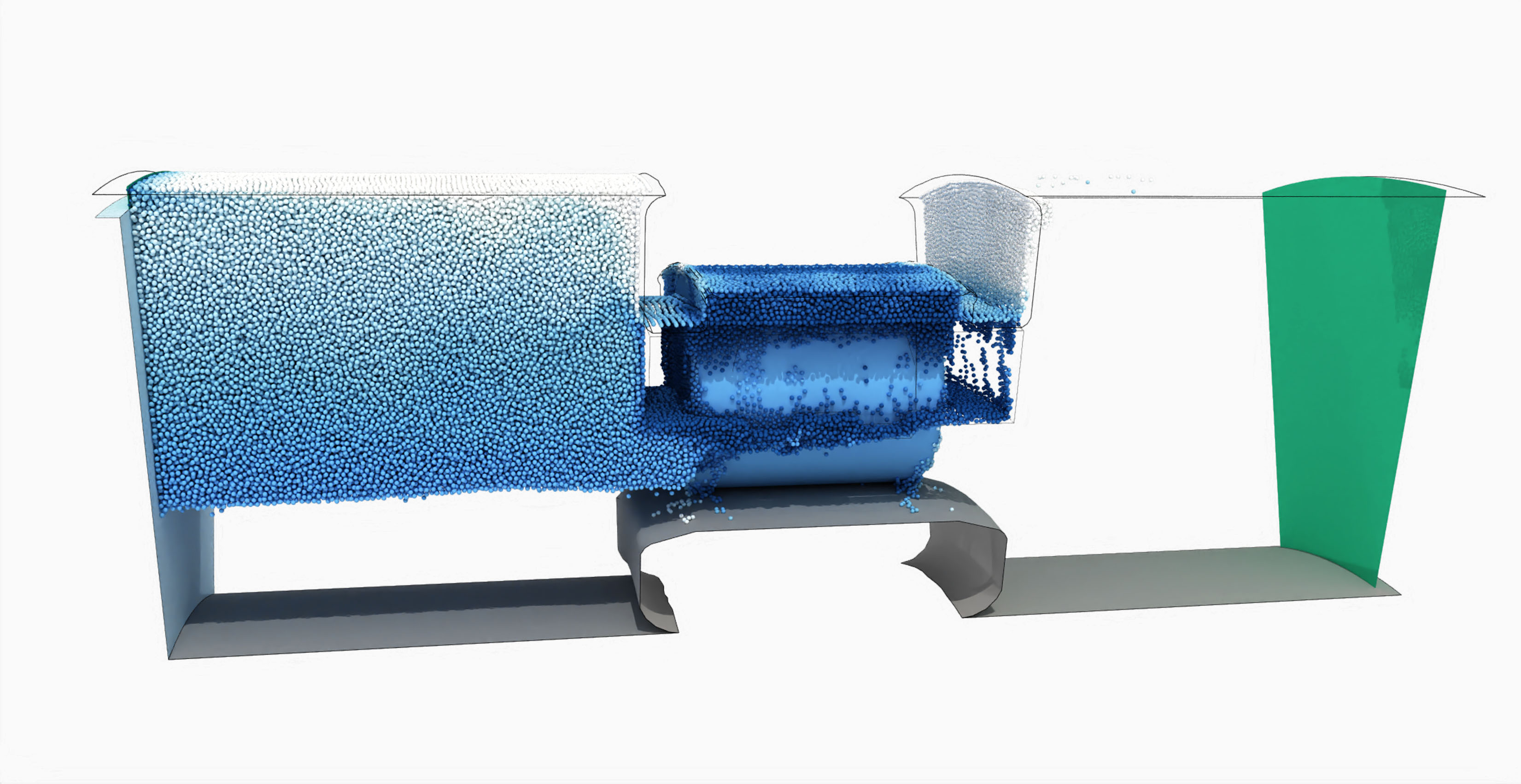
The small gaps around the rolling element restrict the flow through the bearing. As a result, the oil is accumulated in the settling chamber in front of it. The flow in this area shows secondary flows in addition to the main flow in circumferential direction. These can influence the flow to the rolling bearing. Figure 6 shows the averaged flow field in the settling chamber in comparison with the results of a reference simulation.
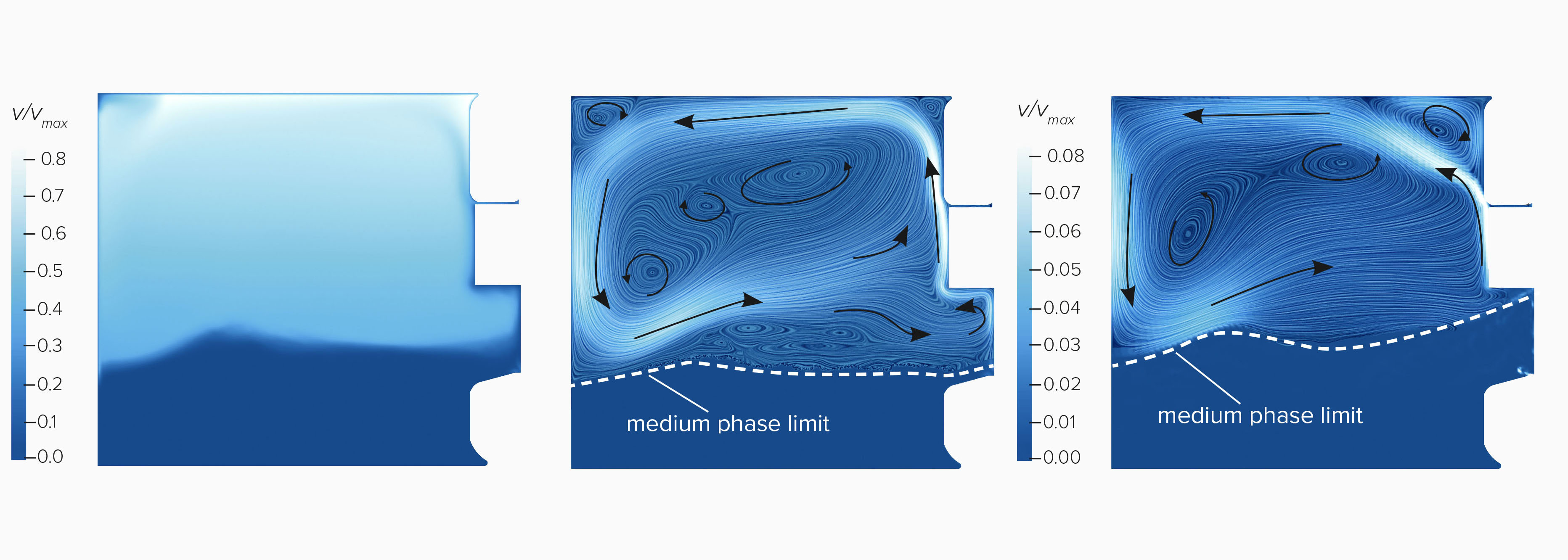
Left: normalized velocity magnitude
Mid: normalized velocity in axial and radial direction
Right: Reference FVM result
And there we have it: the fluid mechanics are comparable between SPH and FVM. The field in the settling chamber is dominated by a large circular secondary vortex. The velocity of this vortex is an order of magnitude smaller than the main flow. Driven by centrifugal force, oil is transported along the cage towards the outer ring and then transported back against the axial flow direction. Furthermore, SPH and FVM generate comparable results for fill level and pressure conditions.
Next step: Let us have a look inside the bearing. In the upper illustration, the flow passes through the bearing in the Z-direction. The small gaps between roller element and outer ring severely limit the maximum possible oil volume flux. Therefore, most of the oil is forced back out of the gap area into the opposite direction. This causes the oil to move against the direction of rotation of the outer ring. As a result, a backflow can be observed between the outer ring and the cage, opposite to the main flow direction.
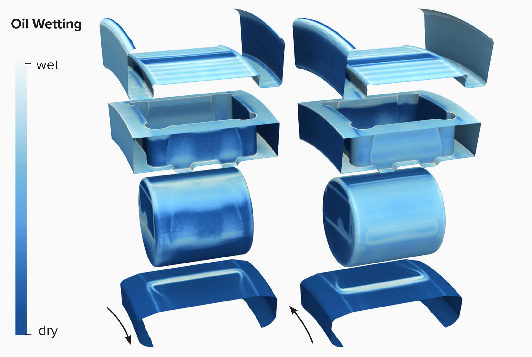
Another point of interest in bearing development is the analysis of the wetting. It is used to ensure that the components are adequately lubricated at different operating points. The wetting analysis uncovers that the back of the rolling element is lubricated significantly less. Due to the selected resolution of this simulation, relatively few particles are found in the gap itself.
Conclusion
In the cooperation between dive solutions GmbH and Schaeffler Technologies AG & Co. KG, roller bearings were successfully simulated with Smoothed Particle Hydrodynamics for the very first time. SPH can answer numerous important questions in everyday engineering applications. These include the determination of oil distribution, oil dynamics, filling level, and pressure conditions. Of course, other interesting results were generated in this cooperation as well, e.g. torque measurement, multiphase simulations, and many more. We discovered that SPH offers the advantages of
- computationally efficient multiphase simulations
- easy realization of single phase flows to further reduce computational effort
- elimination of the overhead of grid generation.
In the development process, it can help to strengthen the position of CFD by
- reducing entry-barriers,
- extending the range of applications, and
- reducing computational effort and simulation turnaround times.
We are convinced that SPH is an important building block for the agile and automated simulation process of the future.
What do you think about these results? What experience have you had with particle-based CFD in the field of the powertrain? Let us know!
1 Sabrowski, P., Beck, L., Wybranietz, T.B: “Modern WCSPH in industrial multiphase application considering complex moving boundaries” (Proceedings of the 14th SPHERIC International Workshop 25-27 June 2019)


