Computational Fluid Dynamics Methods Explained
Types of Methods and Their Uses
This article will give you a basic understanding of the most prominent methods used in Computational Fluid Dynamics (CFD) and touch on some of the newcomers, like the Smoothed Particle Hydrodynamics method. Furthermore, we want to give you some insights into the most favorable fields of application for each method presented. Since this post is meant to be read on the way to work, during breakfast, lunch, coffee or after work, we will avoid using any mathematical formulations. Instead, we will focus on the basic numerical understanding of these approaches.
Importance of Computational Fluid Dynamics
All kinds of engineers deal with fluid flow while working on their specific applications, be it a gearbox, a heat exchanger or the diffusor of a race car. If you are reading this, chances are that you are one of these engineers. Predicting the fluid flow for a new product is a hard task, we feel you! Especially when design cycles are short and many different variants of a product must be assessed in terms of the fluid flow, it is not possible to rely solely on experiments. Over the past few years, simulations with CFD methods have become an integral part of the design process of new products. In CFD, the Navier-Stokes equations (NSE) are discretized and solved on a computer. Because there has been significant development in terms of hardware, the importance of CFD analyses only continues to increase.
Classification of CFD methods
Before we jump in, let us take a look back to the 18th century. Even before the NSE were properly derived, people discussed physical problems like fluid flow in a mathematical manner. Two men in particular, Leonhard Euler and Joseph-Louis Lagrange, had quite differing views when it came to observing fluid flow. This is important even today, as CFD methods are either classified as Eulerian or Lagrangian methods. Using the example of a flowing river (see Figure 1), Euler wanted to observe the river while standing still. Lagrange, on the other hand, preferred to dive into the river and then look around himself while drifting with the current.

Most Eulerian methods utilize a mesh to describe the fluid domain: we subdivide the river into cells and look at it from a distance. If the mesh is not changed, these cells and their neighbors stay the same throughout the simulation. Most Lagrangian methods, on the other hand, do not use a mesh, but rather points which that can move around freely in space. As these points often carry mass and volume, they are called particles. Imagine each molecule of water in the river as a particle. These particles then move with the flow. Their neighboring particles are changing constantly.
With these images in mind, we are finally ready to tech talk and take a closer look at the methods shown in Figure 2. Let us dive right in!

Five Prominent CFD Methods Explained
1. Finite Difference Method (FDM)
Almost everyone who has attended a lecture on Computational Fluid Dynamics will have heard of the Finite Difference Method. The FDM discretizes the NSE on a set of points that hold the physical variables of the fluid e.g. pressure and velocity. These points are usually distributed regularly as this makes things much easier for the implementation. To compute the derivative at a node, a Taylor expansion is utilized. An FDM approximation of first order is shown in Figure 3.

Although the FDM is not the first choice for many applications, it has a place in the CFD world. Especially in applications where a regular grid can be utilized, like weather simulations, the FDM is of interest, as it can be implemented much more efficiently than the FEM or FVM. In addition, it is possible to freely choose the order of the approximation. The more points which are utilized in the approximation of the derivative, the higher the order. The FDM is limited by its dependence on structured grids, making it hard to use such a method for problems involving complex-shaped boundaries.
2. Finite Volume Method (FVM)
When people hear Computational Fluid Dynamics, oftentimes they think of the FVM. Though this is incorrect, FVM is probably the most prominent method in CFD and it can be used for various applications ranging from simulating fluid flow around an airfoil to the thermal simulation of conjugate heat transfer to estimate heat fluxes.
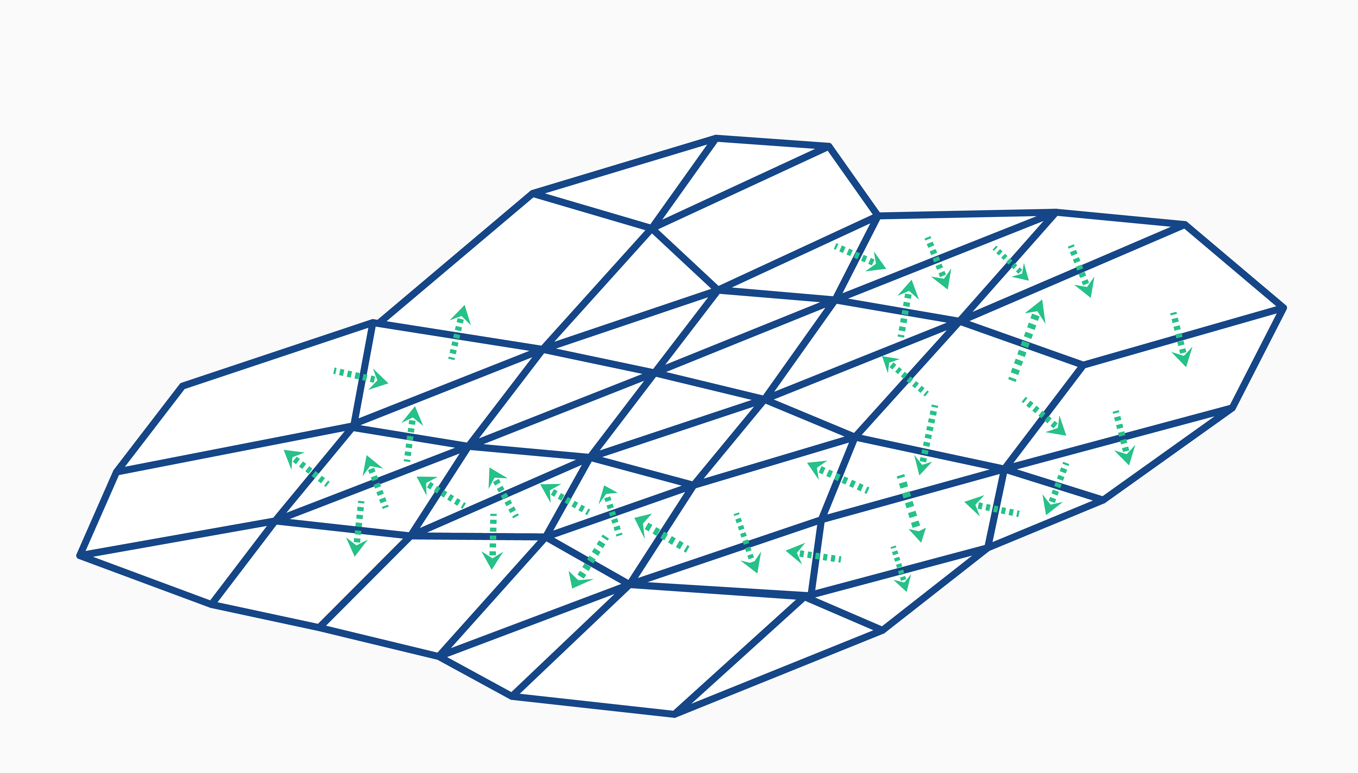
The basic idea of the FVM is to subdivide the whole domain into small control volumes. These volumes exchange fluxes with their neighbors over the respective connecting face. Since the fluxes that enter a cell are leaving another cell, this approach is strictly conservative which makes it very attractive for fluid flow problems. Figure 4 shows this idea in a very simple matter using integrated constant values in each cell.

The FVM is based on an integral version of the NSE and interestingly, the FVM can even be expressed as a special case of the FEM. The method is easy to understand due to the analogy between physical meaning and numerical concept. In FVM, unstructured grids can be utilized, which makes the method very attractive for flows that interact with complex geometries. In case this is a new term: unstructured grids are grids that can be completely arbitrary. Therefore, the grid can also be locally refined such that regions of interest are well-resolved. This is usually done for the region close to the wall. Unfortunately, it is very difficult to increase the order of accuracy of the FVM.
3. Finite Element Method (FEM)
Many associate the term “Finite Element Method” with solving structural mechanics problems. Contrary to this common misconception, the FEM can be used to discretize any partial differential equation, including the NSE. And this is not a novel idea studied by just a few: FEM is actively used to solve fluid flow problems, for example in the field of external aerodynamics.
For the FEM, the space is subdivided into connected elements. In each of these elements, the solution is approximated by piecewise polynomial functions. These are defined by a set of basis functions for every nodal point. These can then be utilized for the estimation of derivatives. In Figure 5, such basis functions are shown for our example. The image also shows basis functions of higher order. These can be utilized to increase the accuracy of the solution. However, another node must then be introduced to each element then.

From a mathematical perspective, the FEM is the land of milk and honey. This is mainly due to its very general derivation via the weak formulation of a physical problem. In addition, increasing the order of the numerical method just by choosing different basis functions is very handy: Which of you has not dreamt of carrying out a CFD simulation with 10th order of accuracy in space before? Like in FVM it is possible to utilize unstructured grids in FEM. This makes the FEM attractive for problems with complicated domains or boundaries. Although using FEM for fluid flow problems seems straightforward – Just start from the NSE, come up with their weak formulation and apply a Galerkin method; easy right? – there are some issues, where a solution has yet to be found. One such example is that the order of the basis functions must differ for the velocity and the pressure.
4. Lattice Boltzmann Method (LBM)
A promising alternative to traditional CFD approaches is represented by the Lattice Boltzmann method. In this method, the Boltzmann equation is used to approximate macroscopic fluid phenomena as mesoscopic shock events of fictitious particles. As the word ‘lattice’ suggests, these calculations take place on a mesh, which is why the LBM is an Eulerian mesh-based method. The LBM algorithm (see Figure 6) is simple, as it consists of just two steps:
- Step 1: streaming, each cell exchanges their fictitious particles with all of their neighboring cells
- Step 2: collision, new mesoscopic quantities are computed based on the particles that were streamed in before
After that, just stream and then collide again. The fluid flow values, such as velocity or density can be computed simply from the mesoscopic quantities in every time step.
Now, some of you might be wondering why it is legitimate to utilize such a method to describe fluid flow. However, it is possible to show that for certain conditions the Boltzmann equation leads to solutions in accordance with the NSE (this is called Chapman-Enskog expansion). This derivation shows that the LBM is equivalent to a second order discretization of the NSE.

Now you might be asking: “Why should I work with the Boltzmann equation instead of the NSE?”. It turns out that utilizing this equation comes with some hefty advantages. From a numerical point of view, the Boltzmann equation is beneficial, as it is easy to find schemes that are purely explicit and exhibit a good locality. The latter means that only neighboring cells communicate with one another. This allows for a very efficient implementation of the LBM and makes it a good candidate for massive parallelization, e.g. using GPUs. This is also the reason why there exist multiple LBM codes out there which beat traditional methods by miles in terms of performance for certain applications like automotive aerodynamics.
In addition, as the LBM is a mesh-based method, many established ideas from the FVM field can be reused, for example multiphase or fluid-structure-interaction approaches. The LBM is still a very young method and many aspects are not yet figured out: In the standard LBM formulation, a homogeneous mesh is required which in turn prevents refining of the mesh.
Additionally, there is a lot of scepticism of CFD engineers towards LBM, as it is not based on the NSE – some people still believe that this method is not actually a Computational Fluid Dynamics method and therefore the results cannot be trusted. This of course is not true, and you now know better.
5. Smoothed Particle Hydrodynamics (SPH)
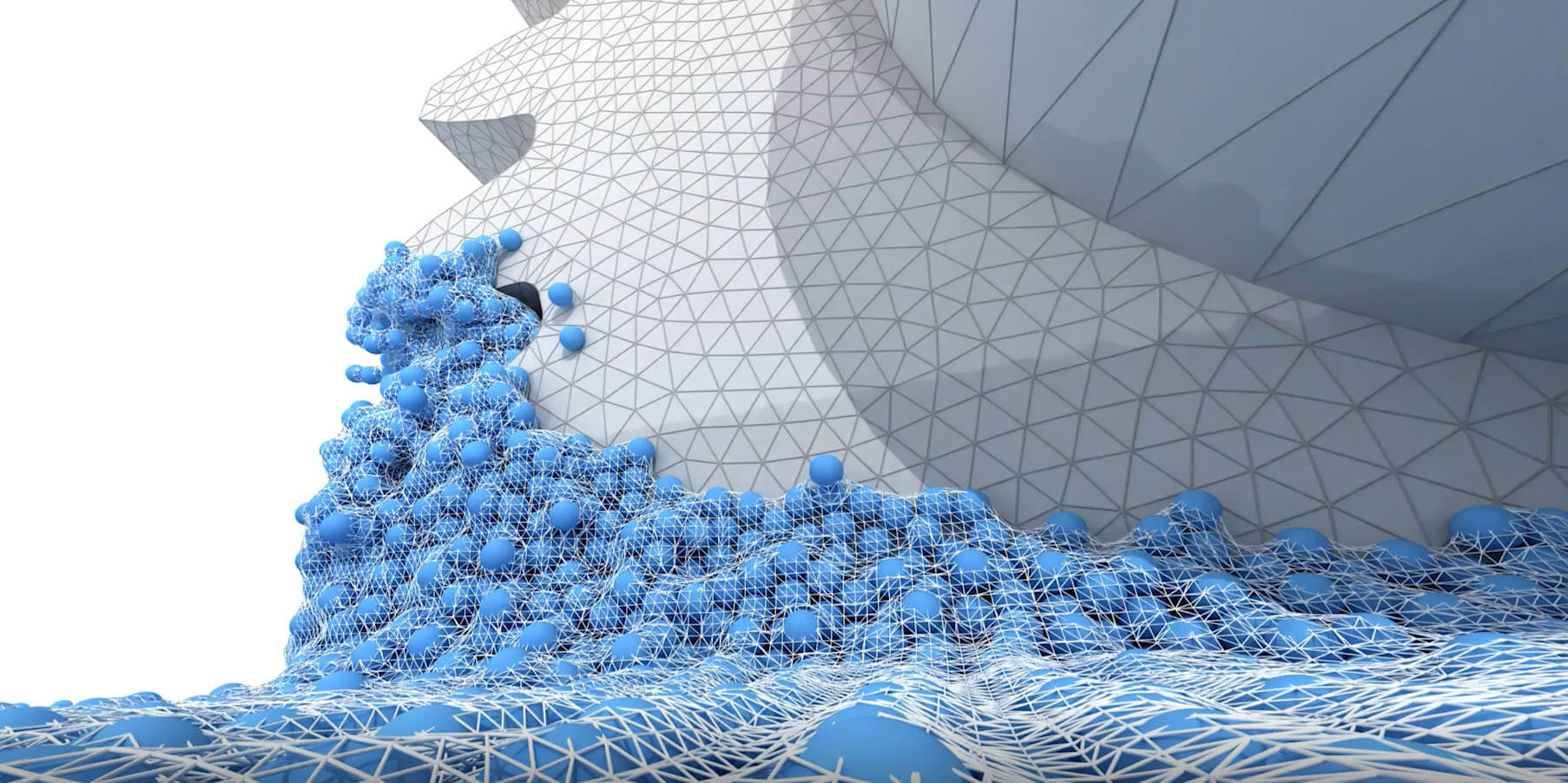
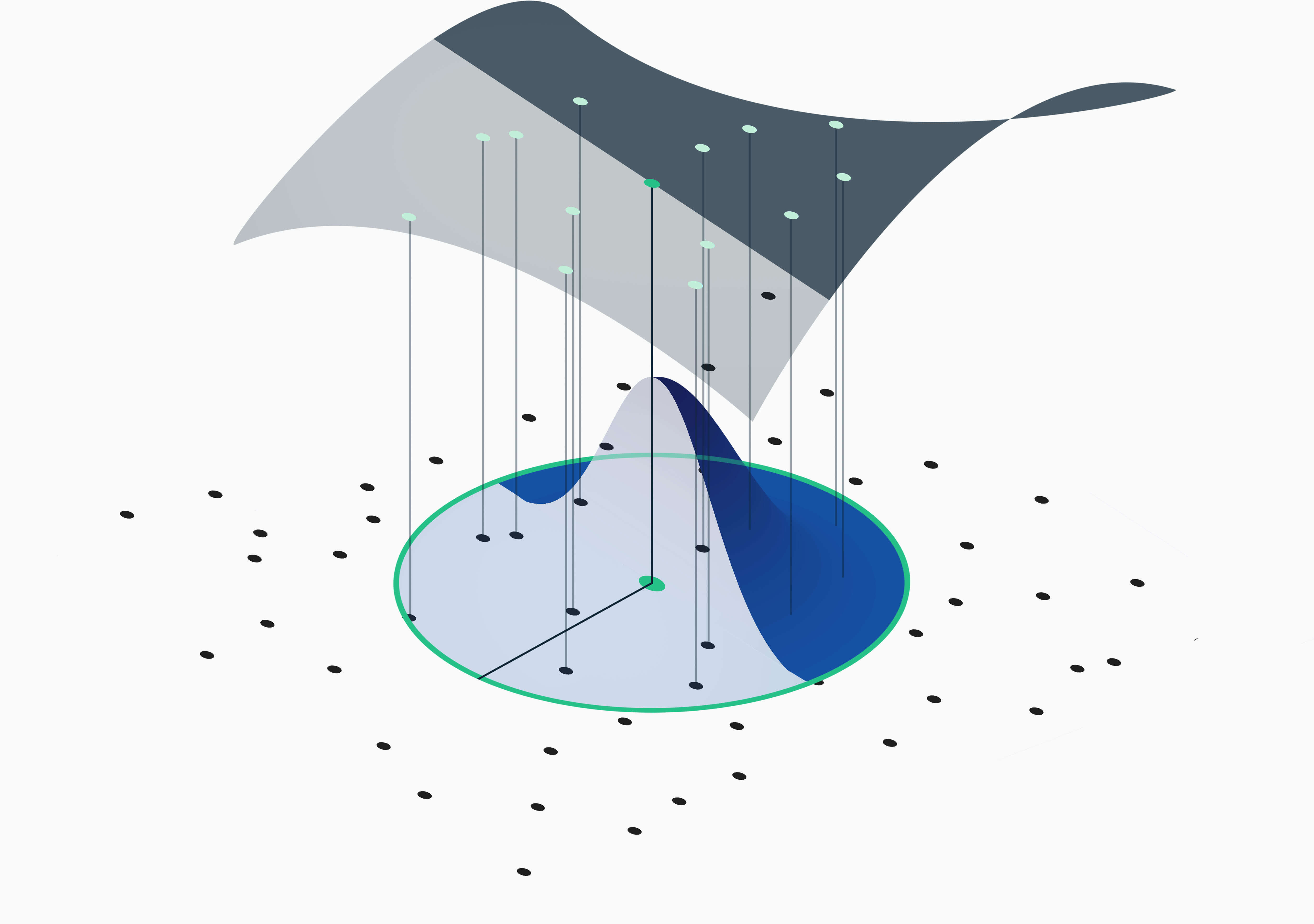
Last but definitely not least is the Smoothed Particle Hydrodynamics method. Like the first few methods mentioned, the SPH method discretizes the NSE to simulate fluid flow. Different to the methods mentioned before, the SPH is a Lagrangian particle-based discretization scheme. Instead of using a mesh, particles are moving around based on their velocity – we put the particles in the river and let them move with the flow. The particles then simply follow the flow: they can detach from another and may come together again later. The derivatives of physical quantities are approximated by weighing the quantities of available neighboring particles (see Figure 7). So-called kernel functions, for example Gaussian kernels, are utilized to calculate the weights.

This unique way of discretizing the fluid field comes with both advantages and drawbacks. As a particle-based method, SPH is especially well suited to deal with flows that are influenced by heavy deformations, like a breaking wave at the beach. Multiphase flows can also be treated easily, as the moving interface between the different phases is tracked inherently. Even moving boundaries and free surface flows are treated efficiently. Hence, the SPH method enables the flow simulation of use cases which were impossible to simulate before.
At this point, we want to mention that SPH itself is usually less efficient than comparable mesh-based approaches when used on phenomena that can already be simulated properly using a mesh. This is due to the costly neighbor-search process, as each particle has to determine which particle is in its proximity in each time step and kernel weights must be computed. Still, mesh-based approaches are limited in terms of use cases and there are lots of applications where the SPH method shines.
From a purely mathematical perspective, the discretization error is hard to formulate for SPH since the particle distribution is always changing. Therefore, mathematicians are still working on this missing scientific piece of the SPH. Nevertheless, in the last five years SPH has made some great improvements and today it has proven to be an incredibly valuable tool for certain industrial fluid flow problems.
Figure 8: Closeup of an SPH simulation in a gearbox. In this situation, the advantages of the SPH method for free surface flows and moving boundaries is clearly visible.
Wrap up
Mesh-based simulation approaches like the FDM, FVM and the FEM are used to accurately simulate fluid flows but struggle with multiphase flows, free surface flows and moving geometries due to their dependency on the mesh topology. This struggle is often based on increasingly complicated preprocessing steps and a bad computational performance due to costly adaptive remeshing algorithms. But let us be clear on that point: these methods are great to solve fluid flow problems without moving parts or even static boundaries. All methods presented have applications where they shine.
Due to impressive performance increases, the LBM is already heavily used by engineers as an alternative to traditional mesh-based approaches. With the help of future research on LBM, this method surely will improve in the coming years and will continue to play a role in Computational Fluid Dynamics.
SPH as a rising CFD method seems to be completely different from all other methods. The particle-based approach allows for the simulation of completely new use cases, especially those that involve highly dynamical fluid flow, like the oil flow in gearboxes, tank sloshing or nozzle simulations. Improved fundamental understanding of the method and improved models will enable even more use cases and might allow for simulations of processes that cannot be captured with an existing simulation method in the future.
We hope that this post busts some myths and assumptions on the mentioned CFD approaches and helps you to gain a basic understanding of the methods and their respective numerical foundations. Are there any other methods you want us to cover? Do you feel that we missed an important aspect of your favorite method? Just reach out to us via social media. If you enjoyed the content stay tuned for our upcoming CAE-related tech posts!


