Gearbox Lubrication
Maximizing Efficiency with SPH Simulations
It’s about time to broaden our view from solely lubrication in gearboxes to what engineering is about — efficiency. This post goes beyond some decently looking visuals. Let’s talk about hard physical facts! So, what are these losses in gearboxes everyone keeps talking about? And why is it worth to not only distinguish but also consider them individually?
Future Demands for Gearboxes and Lubrication Systems
Electrification, e-fuels and hydrogen cars churn up the automotive sector. But they do not make all parts of the drivetrain obsolete! In contrary, components like gearboxes have been and will be one of the central parts to achieve optimum efficiency. Frankly speaking, the upcoming high-speed electric engines will even put more pressure on safety aspects of this part. Large speeds at the gear flanks inherit the risk of a lubrication failure. Due to these rapid movements, the fluid film literally vanishes. Gear flanks are welded together and torn apart. This so-called scuffing damage is likely to destroy the gearbox – potentially leading to complete machinery breakdown. Filling in too much oil might just shift the problem: The gears must push hard to rotate through the oil. A phenomenon called churning becomes prominent.
Efficiency and lubrication are undoubtedly related to one another, but what is the exact connection? Starting more broadly: Which losses are important in which situation and where do they originate from? Using experiments and simulations, this article will attempt to answer these questions and demonstrate
- How to estimate power losses in gearboxes.
- How to measure them experimentally.
- How to analyze churning losses.
- How to find out where these losses originate from.
An Introduction to Power Losses in Gearboxes
Gearboxes are already extremely efficient. Some designs achieve to transform over 99 % of usable mechanical power from in- to output. However, on a large scale this seemingly negligible amount can be quite large. For example, in the case of a 100 MW power plant, this accounts for 1 MW. Speaking in people: This is roughly the power consumption of 1000 people in Germany.
Of course, power cannot be lost, it is simply converted into unwanted heat due to friction. The larger the load, the larger the losses. This share is denoted as load-dependent losses. Similarly, amplifying rotational speed at constant power increases losses as well. These shares are more related to load-independent losses. One can also start to distinguish the shares by components, such as gears, bearings, sealing and auxiliaries. Here, a variety of schematizations exist. One approach is shown in the image below.
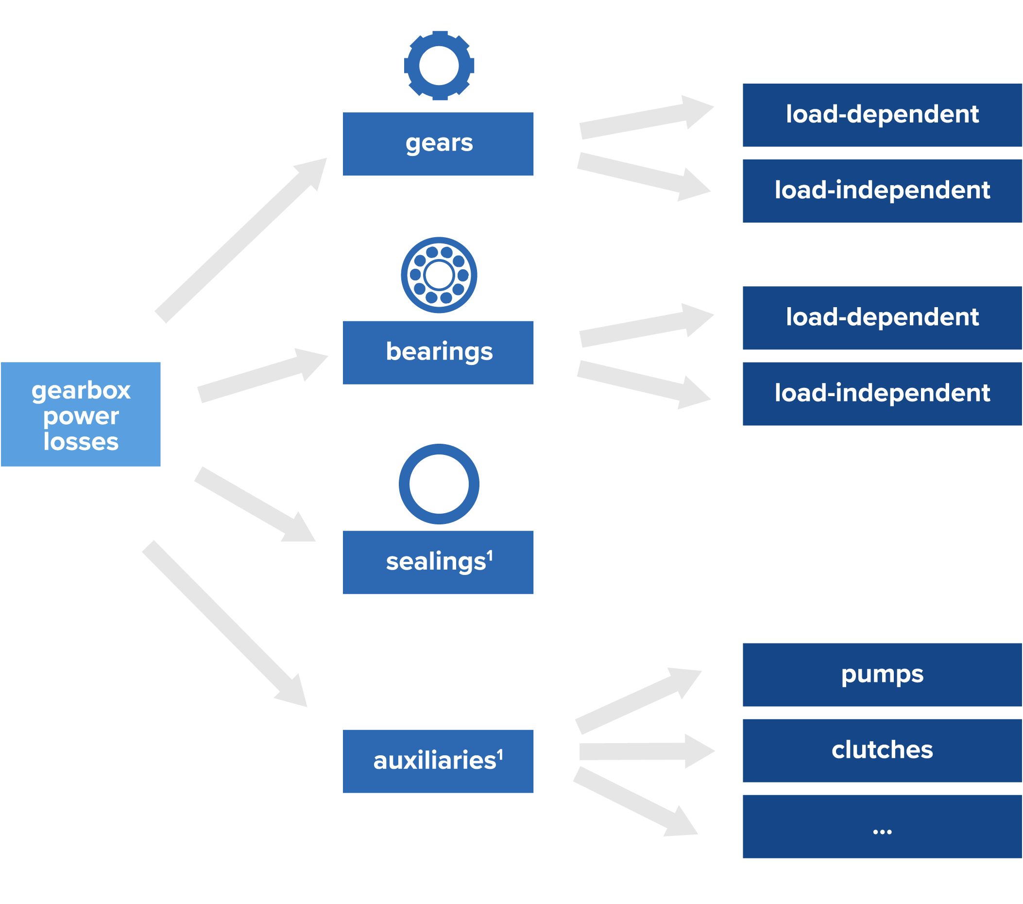
1 Strictly speaking, sealings and auxiliaries are also considered as load-independent losses.
One approach is shown in the image above. Here is another classification that focuses more on the physical origin. There, we also collect information when each loss becomes important.
It is important to consider all of them. Here, we will focus on bevel gears. In a preliminary design, the following tool chain can be applied:
- Load-losses of the gears can be evaluated with the FVA-bevel gear program BECAL2.
- Load-dependent and independent power losses of the bearings can be addressed by the tool SKF Bearing Select.
- Sealing power losses can be taken from the manufacturer catalogue (Freudenberg Simrit GmbH & Co. KG, etc.) for the operating conditions.
- Churning losses of the gears and shafts may be computed by standards or estimation formulas provided in specific publications.
Measuring Power Losses at a Test Rig
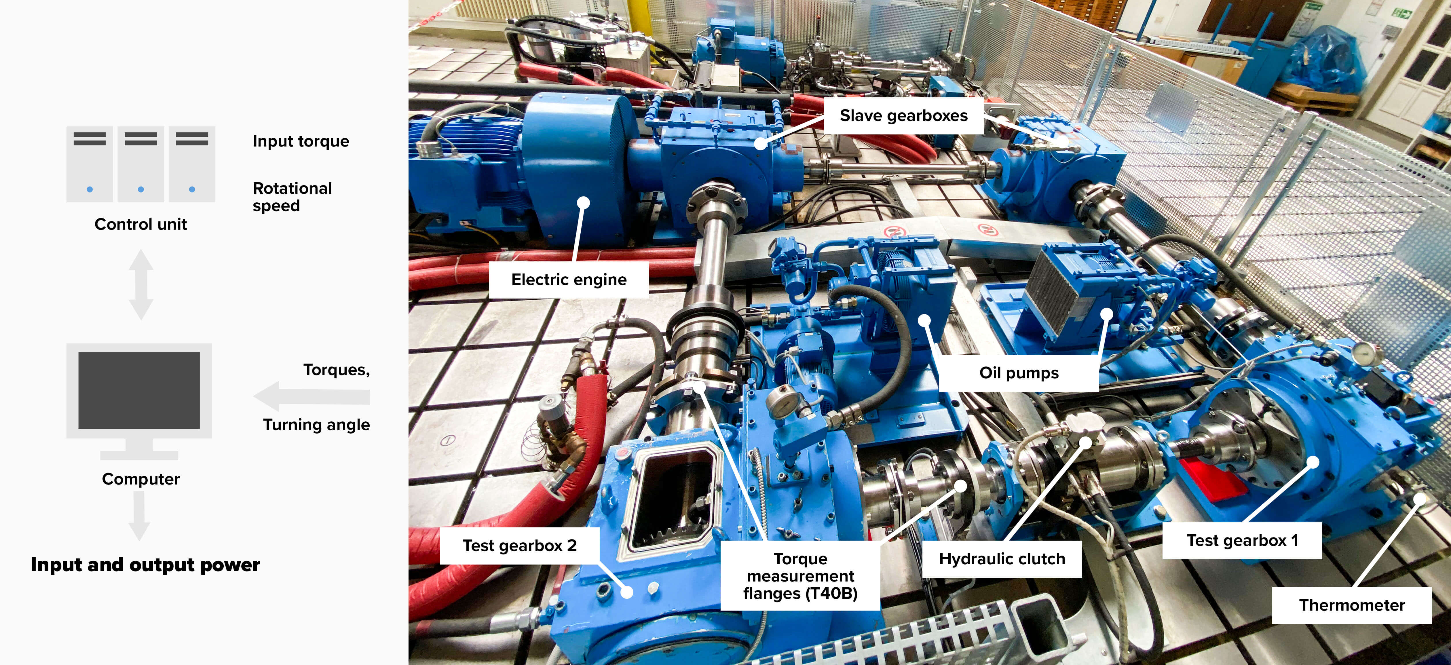
Thanks to the Chair of Machine Elements (IMM) of Prof. Schlecht, Dresden University of Technology, we have been able to take some measurement data from a test rig designed to investigate the load capacity of bevel gears. You can easily imagine how excited we were to conduct experiments for the first time on our own. Once we measured the input and output power for a filled and drained gearbox, load-dependent and load-independent losses could be separated. This method is known as differential measurement.
An image of the whole system is shown below. We focused on the gear train in the test gearbox 2. The torque load is applied via the hydraulic clutch at the pinion side. The torque is entrapped in the arrangement of two slaves and two test gearboxes. Thus, the electric engine compensates all losses for idle mode and adjusts rotational speed. This test rig even allows to investigate the drive and coast mode individually.
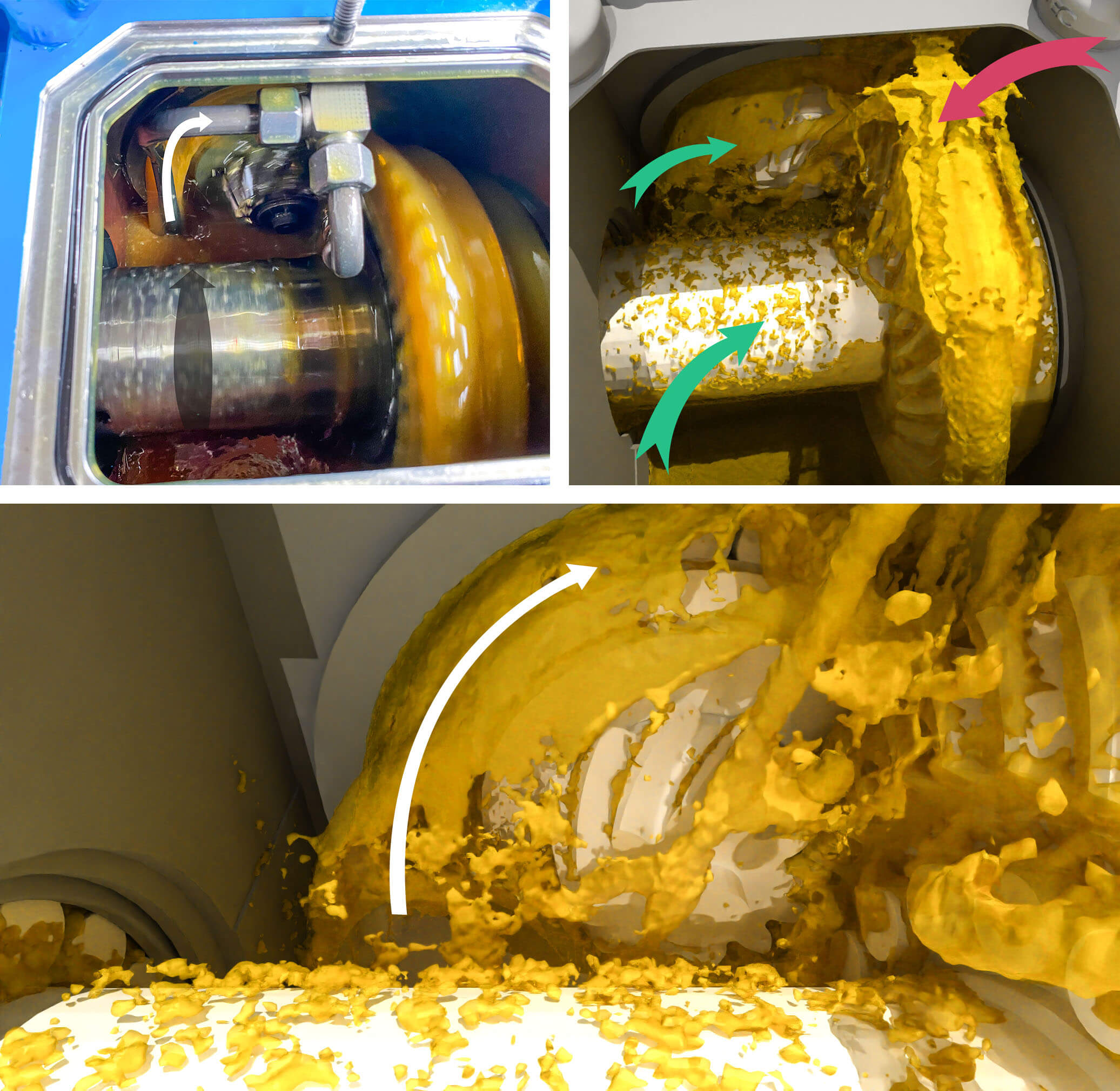
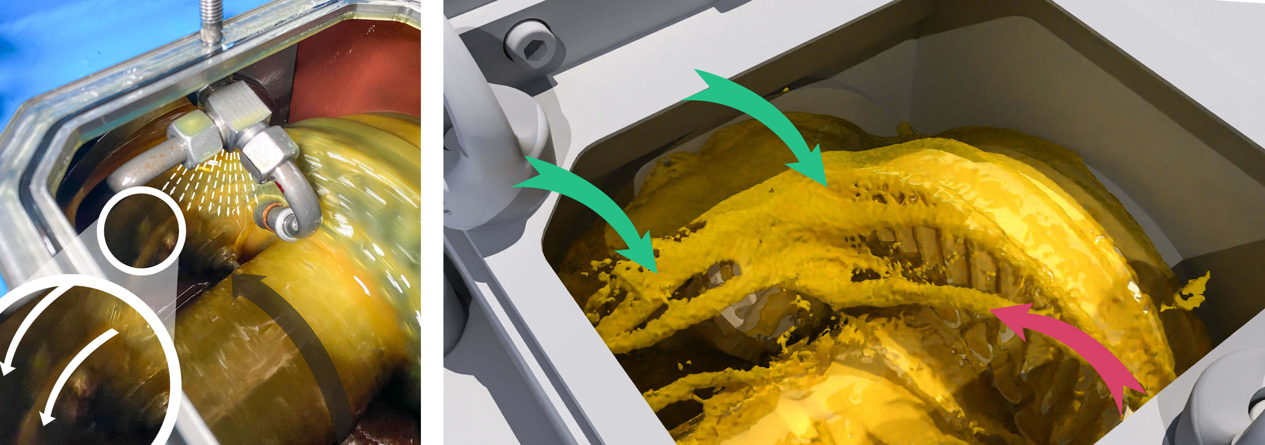
Anyhow, at the beginning we took some images of the cold start at low RPM. Some fascinating flow patterns are seen for different turning directions:
- Oil sticking to the gears.
- Ligaments pumped out by the tapered roller element bearings.
- Droplet break-up and some large oil ligaments emerging out of the surface.
Simulating the Gearbox Lubrication with SPH
We then attempted to replicate these observations with a quick SPH simulation. The flow field in the simulations and the experiment are in satisfying agreement. The matching flow patterns indicate that the fluid dynamics at the higher speeds are reproduced with certainty as well. Unfortunately, the gearbox was not opened under these operating conditions, as to not spill hot oil everywhere in the workshop.
We increased the rotational speed and ran the gearbox idle for some hours. It takes time to reach a thermal equilibrium. During this phase, the oil properties of density, viscosity and surface tension coefficient decrease. Casually speaking, the oil gets thinner. At approximately 60°C (140°F), we took some measurement examples. A comparison with the estimated values is shown below. The results are in a very good agreement. Churning losses are underestimated, and load-dependent losses are overestimated. But what is the reason for the large bearing contribution? Why do the gears not seem to have any meaning here? Doesn’t that contradict intuition?

Wrap up: What you miss out without SPH Gearbox Simulations
Even a highly sophisticated calculation formula will not give a lead on how to answer these questions. This can only be accomplished with numerical simulation. Here, the focus is on the fluid simulation with particle-based methods. Check out our article (CFD Methods Explained: Types of Methods and their Uses) to understand the differences of other CFD methods and why SPH possesses great advantages when it comes to the simulations of gearboxes.
But now, let us dive into the amazing simulation results:
Figure 6 SPH simulation of a bevel geared transmission (gear ratio = 37/12) with tapered and cylindrical roller element bearings. The rotational speed of the pinion is set to 1600 rpm.
Take your time to look at the splash patterns. The wheel expels thousands of droplets into the gearbox domain. However, it also drags some air into the reservoir - between the teeth, there is only a small amount of oil. Evidently, the oil is not really pushed, as it sticks to the components. Thus, shearing of the fluid contributes the most to the losses and drag resistance (equals pressure losses) is not too important. But how can one analyze the losses further? We will do it with local churning losses: Within some areas, losses are accumulated and displayed. In the simulation, we saw that the pinion and its bearings take the largest share (over two thirds) of the losses. Let us investigate that a little bit further.
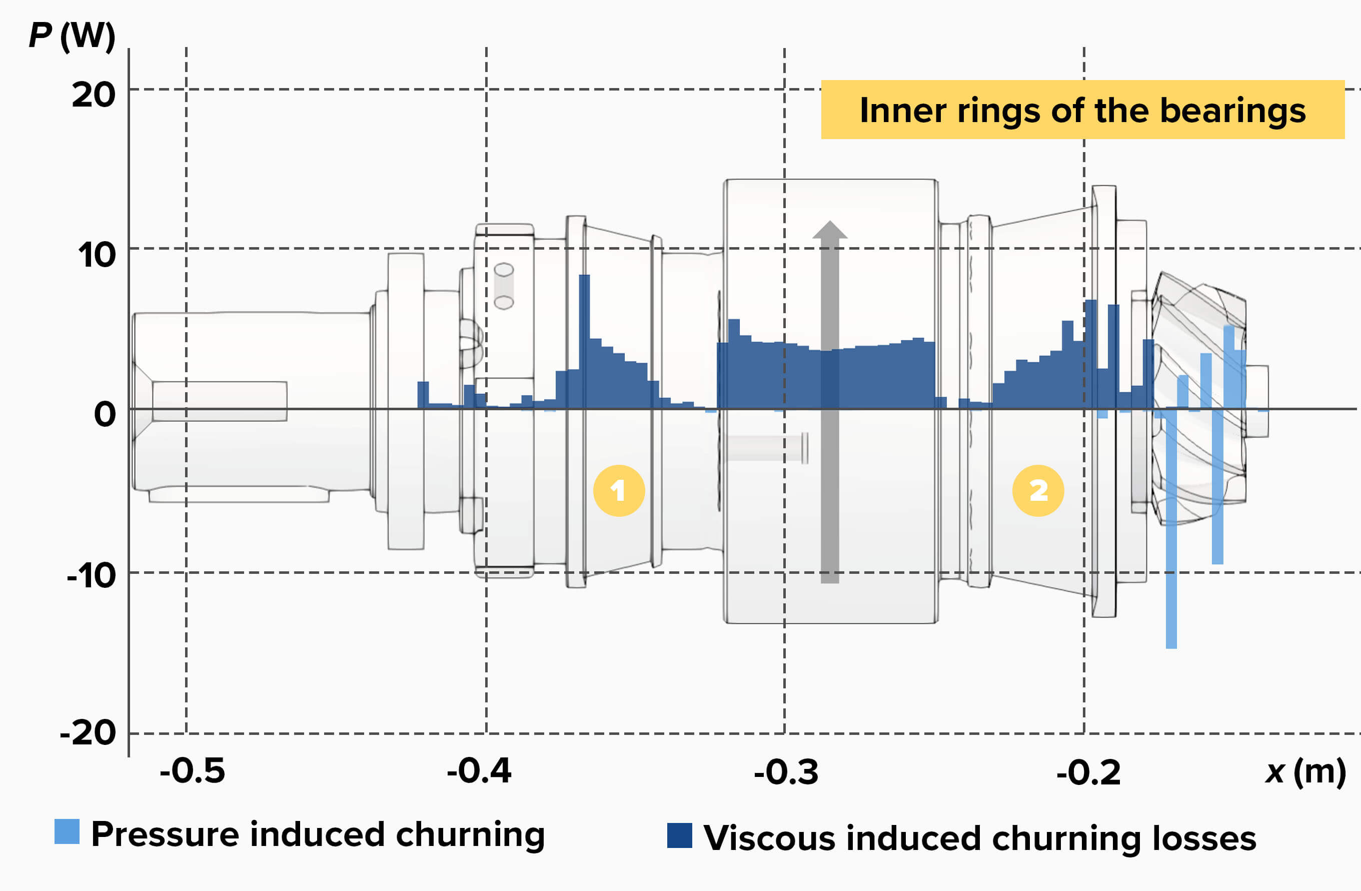
Pressure losses are very small. Some are generated at the gear teeth close to the meshing zone because of squeezing. Here, large amounts of viscous induced losses occur at the inner shoulder and at the inner rings of the tapered roller bearings. The inner shoulder is shrouded. Usually, this is beneficial and reduces churning losses, but here, it is too narrow, resulting in the contrary effect. Of course, this method allows for one to look at the other components as well - for example, the bearings on the pinion.

The large and fast roller elements push oil outwards. They act like a pump. This effect causes a vast amount of pressure induced losses.
Understanding Churning Losses for Your Gearbox Design
In this example, we saw that the viscous losses are large, thus, choosing another oil that suffices the load capacity is a good starting point for optimization. Substituting the heavy-duty automotive lubricant3 with a synthetic oil might not only decrease losses but also optimize the noise, vibration and harshness (NVH) behavior of the whole transmission.
Apparently, the gap at the pinion shoulder is too narrow, so a larger outer diameter might be beneficial here. Lastly, sealing the bearings or selecting a different kind will optimize the efficiency. This is just an example for an academic gearbox. Just imagine the possibilities for transmissions with dozens of gears!
Churning losses, spin losses, no-load losses: Independent of the exact naming, they become critical for high speeds, large gears, or deeply immersed gears. This is particularly true when loads are small, and several gears and bearings are present - a typical situation for the top gear in a transmission. In this situation, these losses can even exceed the load-dependent losses. Analyzing the generation of churning losses and formulating distinct measures is key for high efficiency transmissions. With the progress in CFD, and particularly SPH, this is a low-hanging fruit that can be fetched within hours. Utilizing it enables to optimize the oil management system before it is even built.
If you have any questions, do not hesitate to get in touch with us today. If you have any feedback, I would love to know more about your experience with CAE oil management development or churning loss analysis. Let’s get in contact!
1 Strictly speaking, sealings and auxiliaries are also considered as load-independent losses.
2 BECAL is part of the FVA-Workbench. The latter offers to design a variety of gears like the common types cylindrical, helical and hypoid gears. For these gear types, the individual programs STplus, RIKOR or BECAL can be considered.
3 We used Mobilube HD 80W-90 here.


